Simulating wandering#
In this software reference, you’ll simulate the wandering pipeline in Gazebo. This pipeline is built of multiple components available in the Robotics AI Suite, showcasing how to simulate a complex perception and navigation workload.
wandering is a fully-autonomous mobile robot application that navigates an unknown environment, creating an occupancy grid map and choosing unexplored frontiers while avoiding obstacles, all without human intervention. It combines RGB-D depth camera sensing, multi-sensor point cloud fusion, fast 3D clustering obstacle perception with ADBScan, SLAM mapping, and Nav2 navigation.
Architecture#
The simulation pipeline connects sensor streaming, perception, SLAM, costmap layer integration, navigation, and autonomous exploration:
        flowchart TD
    subgraph Sensors["Sensors & Input"]
        RGBD["Gazebo RGB-D Camera\n(/camera/... /depth/points)"]
        LiDAR["2D LiDAR\n(/scan)"]
    end

    subgraph Perception["Perception & SLAM"]
        Fusion["adbscan_sensor_fusion\n(Time-sync & Voxel filter)"]
        ADBSCAN["ADBSCAN Node\n(3D Clustering)"]
        SLAM["SLAM / RTAB-Map\n(Mapping & Localization)"]
    end

    subgraph Navigation["Nav2 Navigation Stack"]
        Costmap["Costmaps\n(ADBScanLayer + Standard Layers)"]
        NavServer["Nav2 Planner & Controller\n(FollowPath, Recovery)"]
    end

    subgraph Application["wandering_app Package"]
        WanderApp["wandering_app\n(Frontier Exploration)"]
    end

    subgraph Base["Robot Base"]
        Driver["Robot Base Controller\n(Twist / TwistStamped)"]
    end

    RGBD --> Fusion
    LiDAR --> Fusion
    RGBD --> SLAM
    LiDAR --> SLAM
    Fusion -->|"/adbscan/points"| ADBSCAN
    ADBSCAN -->|"/obstacle_array"| Costmap
    SLAM -->|"/map & TF"| Navigation
    Costmap --> NavServer
    Costmap -->|"/global_costmap/costmap"| WanderApp
    WanderApp -->|"NavigateToPose action"| NavServer
    NavServer --> Driver
Data Flow & Component Roles#
Sensors & Input: The composed TurtleBot3 Waffle RGB-D robot model simulates both a 2D planar LiDAR (
/scan) and a generic RGB-D depth camera publishing color images, depth images, camera info, and depth point clouds (/camera/depth/color/points).Sensor Fusion (
adbscan_sensor_fusion): Theadbscan_pointcloud_fusionnode time-synchronizes planar scan and 3D depth point clouds, transforms them into thebase_linkframe, combines and voxel-downsamples them, and publishes/adbscan/points.3D Obstacle Perception (
adbscan_ros2): The ADBSCAN clustering node runs 3D density-based spatial clustering on/adbscan/pointsand publishes object-sized 3D bounding obstacles to/obstacle_array.SLAM & Mapping: RTAB-Map (
slam_backend:=rtabmap, default) performs visual RGB-D mapping and localization, publishing the/maptopic andmap$\rightarrow$odomtransform. Alternatively, SLAM Toolbox (slam_backend:=slam_toolbox) can be selected for 2D LiDAR SLAM.Nav2 Costmap Integration (
nav2_adbscan_layer): The customADBScanLayerplugin integrates with Nav2’s global and local costmaps. For each detection in/obstacle_array, it marks a lethal circular obstacle region with configurable padding and timeout expiration. Standard obstacle and inflation layers run alongside it.Autonomous Frontier Exploration (
wandering_app): Thewandering_mappernode inspects the global costmap for free, unexplored frontier boundaries and issuesNavigateToPoseaction goals to Nav2.
Components#
wandering_bringup: Launch orchestration, Gazebo model spawner, ROS-Gazebo sensor bridge, and RViz configurations.adbscan_sensor_fusion: Multi-sensor point cloud fusion and voxel downsampling.adbscan_ros2: Fast 3D point cloud clustering node producing/obstacle_array.nav2_adbscan_layer: Custom Nav2 costmap plugin (ADBScanLayer) marking detected obstacles.rtabmap_ros/slam_toolbox: Visual RGB-D SLAM or 2D LiDAR SLAM backends.Nav2: Upstream path planning, controller, and recovery server.
wandering_app: Autonomous frontier exploration node and RViz Wandering Control panel.
Source Code#
The Wandering source code is available with the Robotics AI Suite.
Run the Gazebo Simulation#
This tutorial demonstrates the autonomous mapping and exploration pipeline using the composed TurtleBot3 Waffle RGB-D robot in Gazebo. For more information about TurtleBot3 Waffle, refer to the TurtleBot3 documentation.
Prerequisites#
Complete the Getting Started guide before continuing.
If your system has an Intel® GPU, follow the steps in the Getting Started guide to enable GPU acceleration for simulation.
Install the Application#
Install the wandering metapackage for your installed ROS 2 distribution:
sudo apt update
sudo apt install ros-jazzy-wandering
sudo apt update
sudo apt install ros-humble-wandering
If you are developing or building from source, build the application using the make build target:
ROS_DISTRO=jazzy make build
source install/setup.bash
ROS_DISTRO=humble make build
source install/setup.bash
Launch the Simulation#
By default, graphical Gazebo client rendering (gui:=false) is disabled to save system resources, while the physics simulation and sensor pipelines are executed in the backend by the Gazebo server (gz-server). If you wish to open the graphical Gazebo window alongside RViz, pass gui:=true.
Execute the command below to start the autonomous simulation pipeline:
ros2 launch wandering_bringup wandering_sim.launch.py gui:=true
Note
By default, gui is set to false in wandering_sim.launch.py. The Gazebo simulation continues running headlessly in the backend via Gazebo server, significantly reducing GPU and CPU resource overhead while RViz handles visualization. Omit gui:=true when running on resource-constrained systems, headless test nodes, or automated benchmarks.
What this starts:
Gazebo Sim with composed RGB-D Waffle: Starts the backend Gazebo server world and spawns the TurtleBot3 Waffle equipped with an RGB-D camera payload (
gui:=trueoptionally opens the graphical Gazebo client window).RGB-D Sensor Bridge: Translates simulated camera color, depth, camera info, and depth point cloud streams to ROS 2 topics.
SLAM & Nav2: Starts RTAB-Map SLAM (or SLAM Toolbox) alongside Nav2 configured with
ADBScanLayerin both local and global costmaps.ADBSCAN 3D Perception: Fuses point cloud data and clusters obstacles into
/obstacle_array.Frontier Exploration (
wandering_app): Evaluates costmap frontiers and sendsNavigateToPosegoals to Nav2.Visualization:
Global map RViz window with the Wandering Control panel.
Local costmap RViz window displaying real-time obstacle layers.
rqt_image_viewwindow displaying the camera color feed.
Expected output:
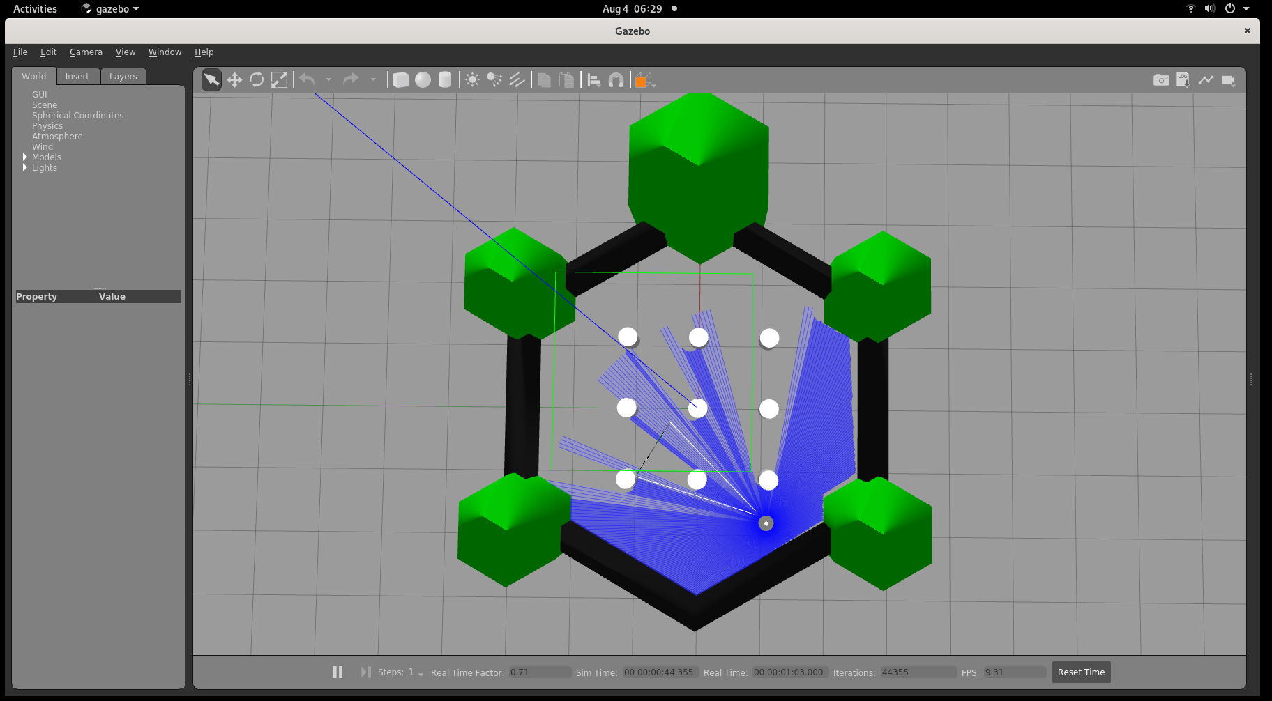
When gui:=true is specified, the Gazebo simulation environment opens:
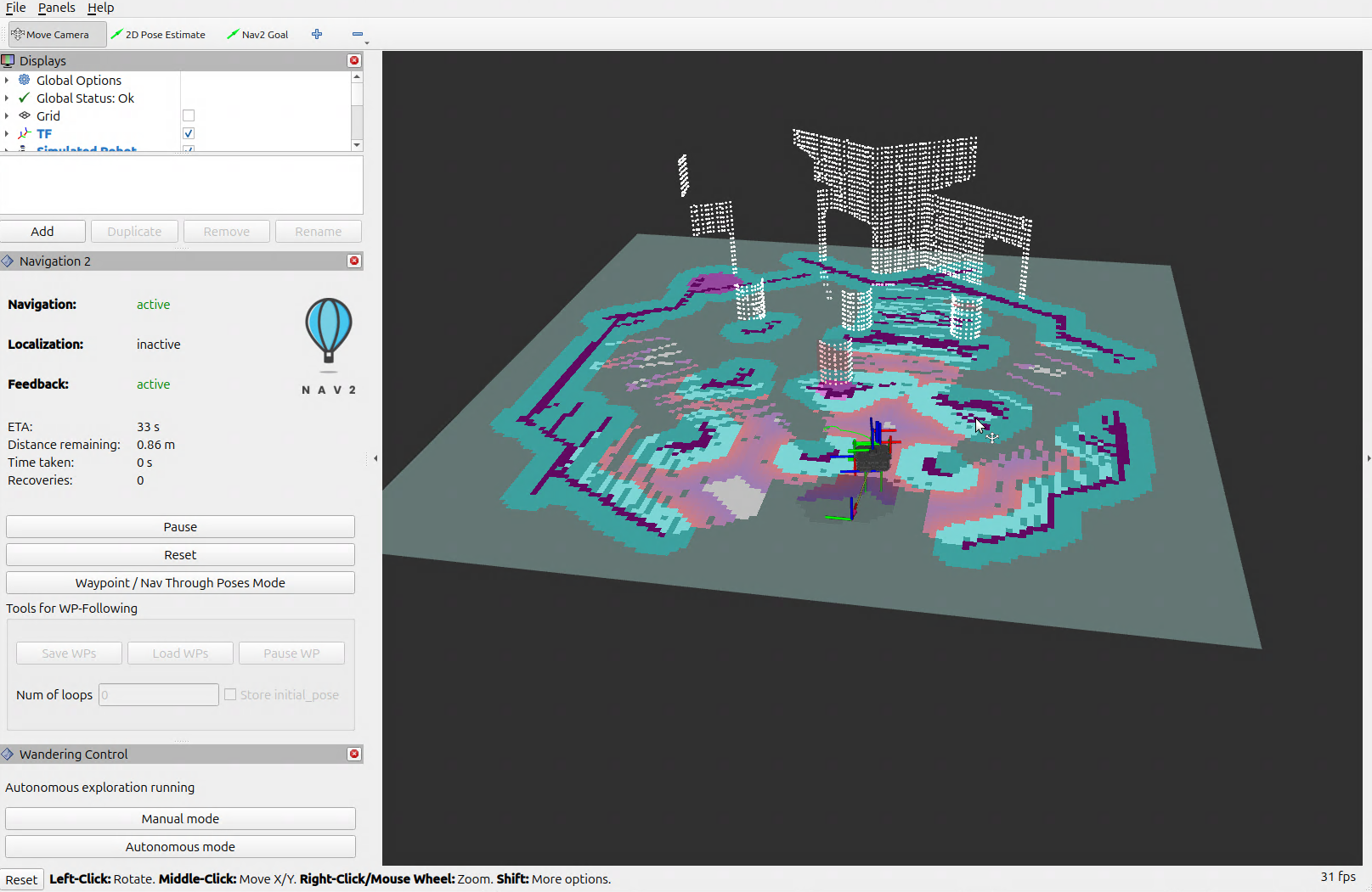
RViz displays the mapped area, costmaps, and robot position:
To enhance simulation performance when the Gazebo GUI is running, set the real-time update rate in Gazebo:
In Gazebo’s left panel, go to the World tab and select Physics.
Set the Real Time Update Rate to
0.
To stop the simulation, press Ctrl-c in the terminal where the launch command is executing.
Selecting a SLAM Backend#
By default, the simulation uses RTAB-Map for visual RGB-D SLAM. To use SLAM Toolbox (2D LiDAR SLAM) instead:
ros2 launch wandering_bringup wandering_sim.launch.py \
  slam_backend:=slam_toolbox gui:=true
Headless Execution#
To run the simulation in headless mode without the Gazebo graphical window (the default launch behavior):
ros2 launch wandering_bringup wandering_sim.launch.py
This runs the Gazebo server in the backend to manage physics and sensor generation without the rendering overhead of the Gazebo GUI client. You can also pass use_rviz:=false if running on purely headless servers or automated CI pipelines:
ros2 launch wandering_bringup wandering_sim.launch.py use_rviz:=false
Velocity Message Conventions#
The simulation launch file handles command velocity stamping automatically:
Jazzy + Gazebo Harmonic: Uses
geometry_msgs/msg/TwistStamped(enable_stamped_cmd_vel: true).Humble + Gazebo Classic: Uses
geometry_msgs/msg/Twist(enable_stamped_cmd_vel: false).
Troubleshooting#
1. Simulation Stutter or Low Real-Time Factor#
Symptom: Low simulation frame rate or high host CPU/GPU load.
Remedy:
Run the simulation in headless/server-only mode by omitting
gui:=true(the default behavior).In Gazebo’s left panel, go to World $\rightarrow$ Physics and set Real Time Update Rate to
0.Ensure Intel GPU hardware acceleration is configured according to the Getting Started guide.
2. Robot Remains Stationary#
Symptom: Nodes launch successfully, but the simulated robot does not drive toward exploration goals.
Root Cause: Simulation clock is not advancing, or velocity stamping mismatch.
Verification:
ros2 topic hz /clock
ros2 topic hz /cmd_vel
Remedy: Ensure Gazebo physics is playing (click the Play button in Gazebo GUI if paused). If custom parameters are supplied, ensure
use_sim_time: trueis configured on all Nav2 and application nodes, and check velocity stamping (TwistStampedon Jazzy vs.Twiston Humble).
3. Verifying Sensor Data Streams#
If costmaps do not update, confirm that the Gazebo RGB-D sensor bridge is streaming data to ROS 2 topics:
ros2 topic hz /scan
ros2 topic hz /camera/color/image_raw
ros2 topic hz /camera/depth/color/points
ros2 topic hz /adbscan/points
ros2 topic echo /obstacle_array --once
For general system and middleware issues, refer to the troubleshooting guide.
Next Steps#
You’ve completed the simulation software reference. Continue to the
deployment learning path and see
Deploying wandering on Clearpath Jackal to run the
workflow on physical robot hardware.